About Speedframe
How to design your speedframe project
- Available in aluminium with a suite of 14 different sections to choose from
- DIY flat packs
- No painting or welding required
- Cut to length service available
- Design and installation are on us
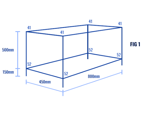
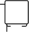
1. Sketching the unit
Make a simple sketch of the unit to be built. Show tube lengths and joint numbers (Figure 1). (To calculate overall dimensions add 1.6mm to tube length for each insert and 25.4mm for each joint). Beside the sketch, make a list of materials needed – tube lengths, joints, inserts, shelf supports, shelving material etc., referring to the Speedframe Components Guide.
List of materials
(Dimensions shown refer to tube lengths)
Square tube joints
- 4 off 800 mm = 3200 mm
- 4 off 500 mm = 2000 mm
- 4 off 450 mm = 1800 mm
- 4 off 150 mm = 600 mm
Total = 7600 mm
Joints
- 4 off 4.1 (1 pkt)
- 4 off 5.2 (1 pkt)
Accessories
- 28 off Inserts
- 4 off Adjustable Feet
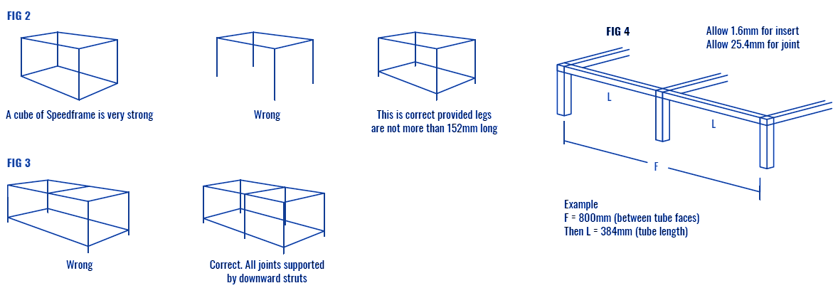
2. Design Rules
Alloy Speedframe
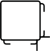
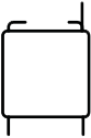
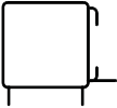
(i) Intercepted members must never be load -bearing unless they are supported by a downward strut (Figure 3). When calculating lengths of intercepted members allow for size of joint and inserts (Figure 4).
3. Cutting
If not using ready-cut lengths, cut tube to size using a hacksaw or cut-off saw. For maximum economy, cut longest lengths first. Carefully remove burrs from cut ends of the tube using a file.
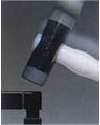
4. Making Joints

Important
Failure to properly apply the design and assembly instructions contained herein may result in you building an unsafe structure. If in any doubt whatsoever, contact your local Speedframe centre for advice before proceeding.
Push insert into open end of tube. Select the joint required and push the arm of the joint into end of tube. Strike the head of the joint (not the arms) with the white face of the Speedframe hammer to drive the joint home, the insert will then retain it firmly in place. Avoid hammering open ends of tube – interpose a piece of wood. Speedframe frame-works can be dismantled by knocking apart with the Speedframe hammer.
Joints can be screw fixed to safeguard them coming out. Make sure the joint is properly home. Drill a 3.5mm hole approximately 10mm from the end of the tube. Drill through one side of the tube and right through the joint making sure that the hole does not penetrate the opposite wall of the tube. Screw fix with appropriate self- tapping screw.
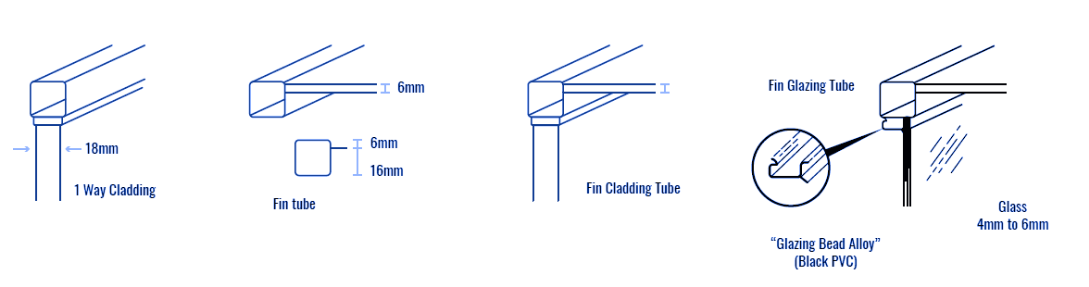
5. Tube Profiles
The Alloy Speedframe system comprises a range of extruded aluminium tubes, with joints and inserts as for the steel system. These extrusions cater for a wide range of cladding and glazing requirements and allow considerable flexibility in designing display partitioning and exhibition applications. The natural anodised finish, with colour/matched joints, is durable and aesthetically pleasing.

- Plain tube
- 25mm square

- 1-way
- cladding tube
- 2-way cladding
- tube (opposite)
- 2-way cladding
- tube (adjacent)
- 3-way
- cladding tube

- Fin tube
- Fin-cladding
- tube
- Fin-glazing
- tube

- 1-way
- glazing tube

- 2-way
- glazing tube (opposite)
- 2-way glazing
- tube (adjacent)
- Glazing-cladding
- tube (opposite)
- Glazing-cladding
- tube (adjacent)

- Glazing bead
- Alloy

- Double fin (opposite)
All tubes are 25mm square, extruded from aluminium alloy in natural finish and clear anodised. Cut Lengths: In any size from 102 mm to 3658 mm. Glazing bead-Alloy is supplied in 2540 mm nominal lengths. Refer to Page 6 for Tube Profile part no.
Download the product guide
6. Assembly
- Mitre fins of the section, if necessary, using nylon template and clippers or fine toothed hacksaw.
- Cladding must be fitted before framework is completed.
- Glass can be inserted after framework is completed as it is retained by snap-in bead.
1. JOINTS
Standard Speedframe joints provide the seven possible right-angle intersections of square tube. The joints are pressure die-cast in aluminium alloy and stove- enamelled to simulate the finish of the tubes. Joints type 6.6 are supplied unfinished as they are not visible when assembled.
2. APPLICATIONS